Overview
In this project, I explored and implemented a variety of geometric mesh operations. The most basic element of a mesh is a curve, defined by a set of control points. I first constructed Bezier curves from a set of control points with de Casteljau’s algorithm. Using 1D de Casteljau, I interpolated between a 3D grid of 16 control points to create a Bezier surface patch. With the geometry constructed, I was able to implement a series of local mesh operations that are useful for manipulating meshes and adding greater detail. Next, by traversing through the half-edge data structure I averaged mesh normals. I took the cross product of triangle edges, which produced a weighted average when iterating through the mesh structure. The edge flip operation was more complex, since I kept track of many pointers and reassigned every half-edge, edge, vertex, and face. Similarly, the split operation involved many pointers, but required additional elements. Finally, I was able to put the edge split and flip to use when implementing loop subdivision and upsampling. At a high level, this process includes the splitting of every edge in the original mesh and flipping new edges that touch both new and old vertices. Overall, this project felt like a peek into the tools behind 2D and 3D softwares such as Maya and Illustrator. I enjoyed familiarizing myself with the half-edge data structure so widely used throughout graphics.
Section I: Bezier Curves and Surfaces
Part 1: Bezier curves with 1D de Casteljau subdivision
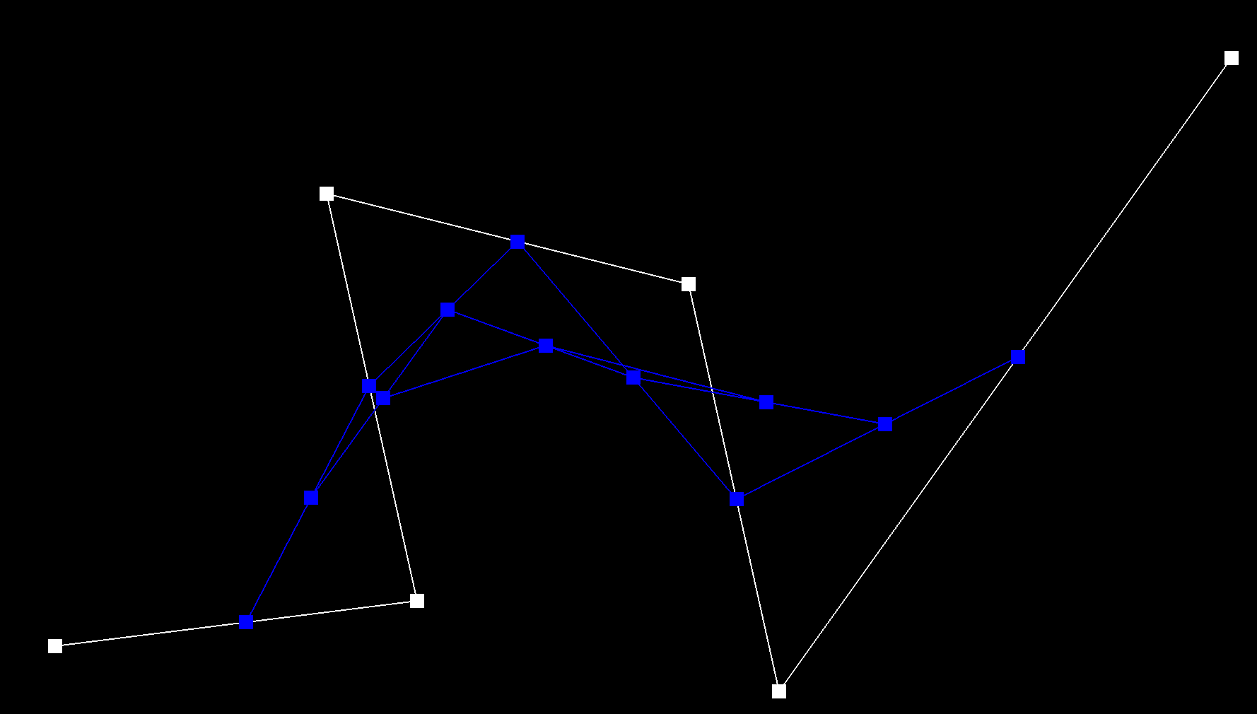
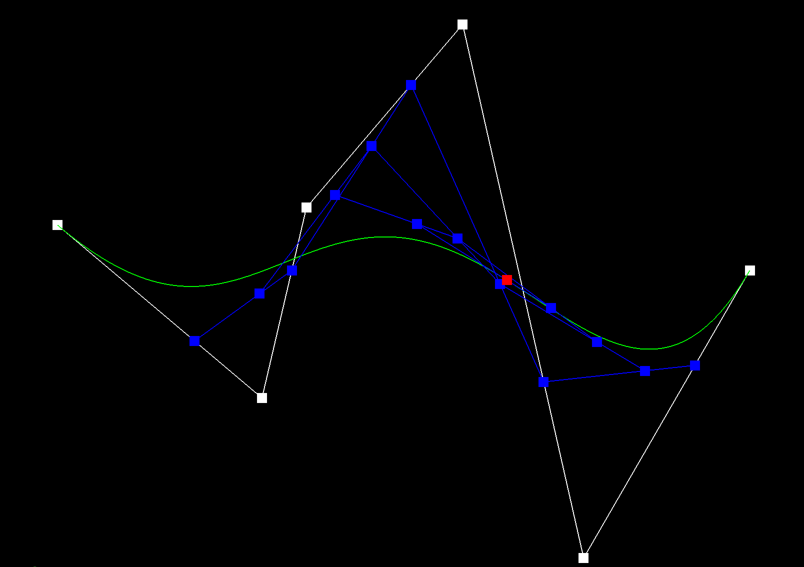
In part one, I implemented the intermediate step of evaluating Bezier curves using de Casteljau’s algorithm. I completed the evaluateStep() function to compute the control points at the next level of the curve. Linear interpolation between control points(n points) and interpolation value "t" of the previous level gives us the control points of our next level (n-1 points). Each call to this function gives us the next level of controls and is called until the number of points gets down to one. With the final control point calculated, the curve evaluation is complete. Below are images of my own curve at each level of evaluation.
 control points
|
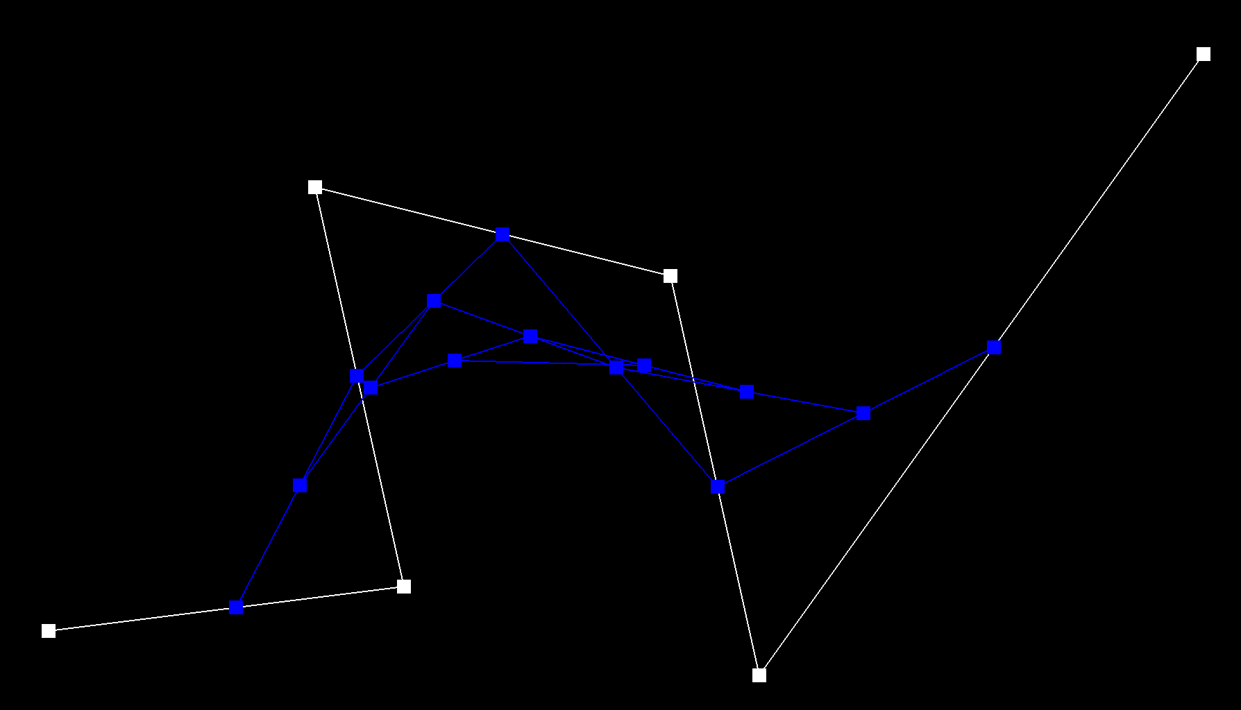
 first level of evaluation
|
 second level of evaluation
|
 third level of evaluation
|
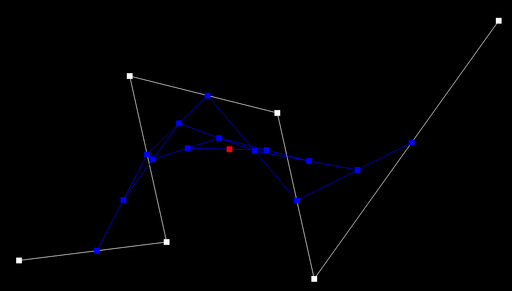 final point evaluated
|
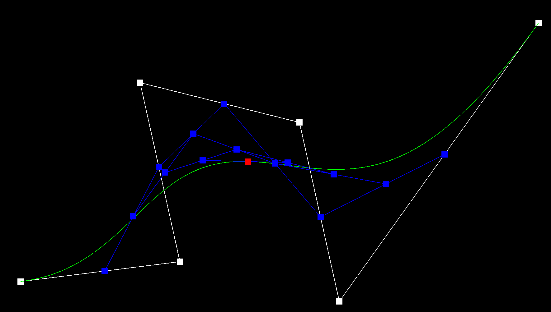 final curve
|
 moved control points and toggled "t" value
|
Part 2: Bezier surfaces with separable 1D de Casteljau subdivision
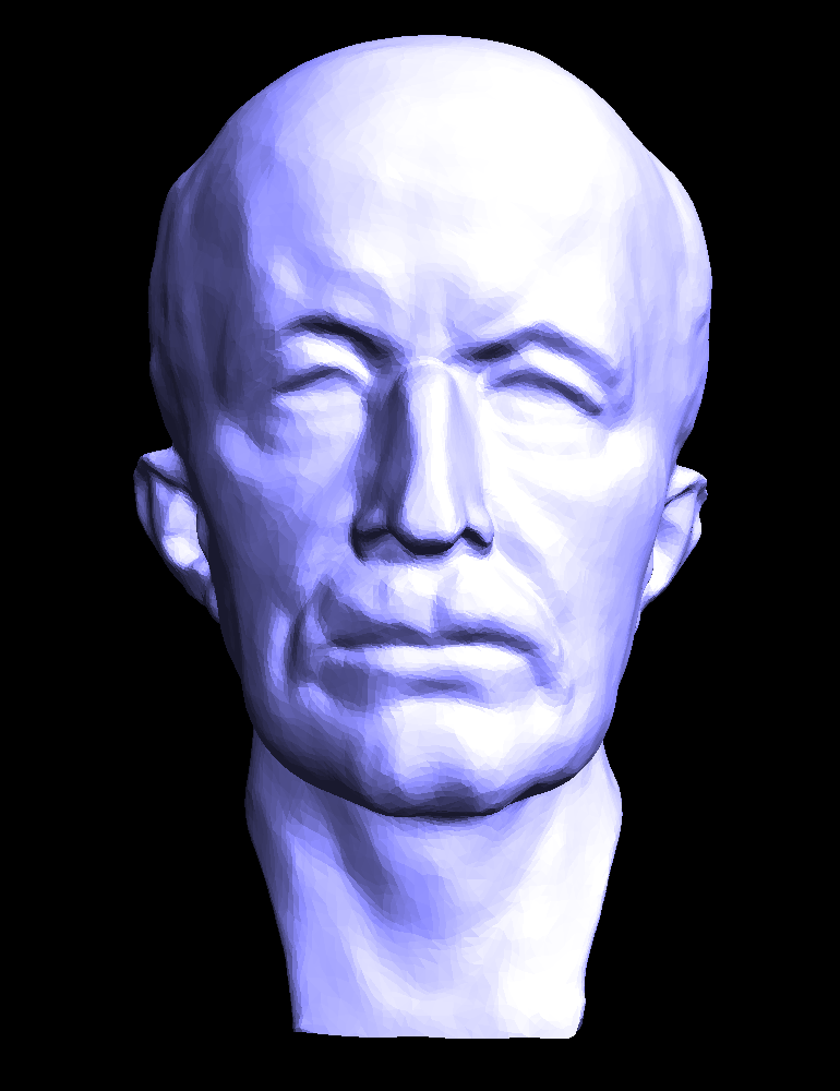
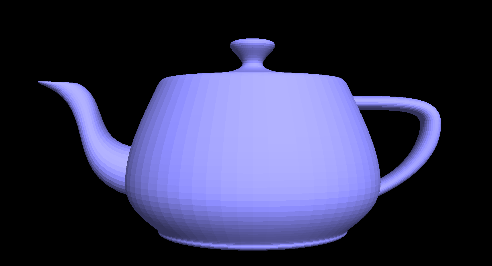
Bezier surfaces, represented with 16 control points, can be interpolated using the same fundamental principle used in part one with Bezier curves. In part two, I applied the 1D de Casteljau’s algorithm to the surface (Vector3D points) in each direction to get the separate curves in the x, y, and z directions. I performed these operations in the evaluate1D() function that calculates the Bezier curve for 4 points that lie on a single curve. After those were evaluated, I interpolated once more between those new points to get the final three-dimensional curve. Below is a render of the Utah Teapot mesh.
 Utah Teapot
|
Section II: Sampling
Part 3: Average normals for half-edge meshes
Part three consisted of averaging normals for half-edge meshes. By calculating the area-weighted normal vector at each vertex, the surface appears much more smooth than before averaging the normals. I created a reference to the first half-edge of the mesh to be used in the the loop that goes through the entire mesh patch. I took the cross product of the triangle edges, which yielded a vector that was already area-weighted. I advanced the half-edge for the next iteration and returned the unit vector of averaged normals once the mesh was fully traversed.
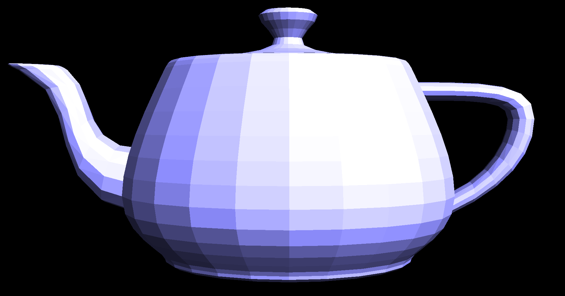 teapot render without averaged normals
|
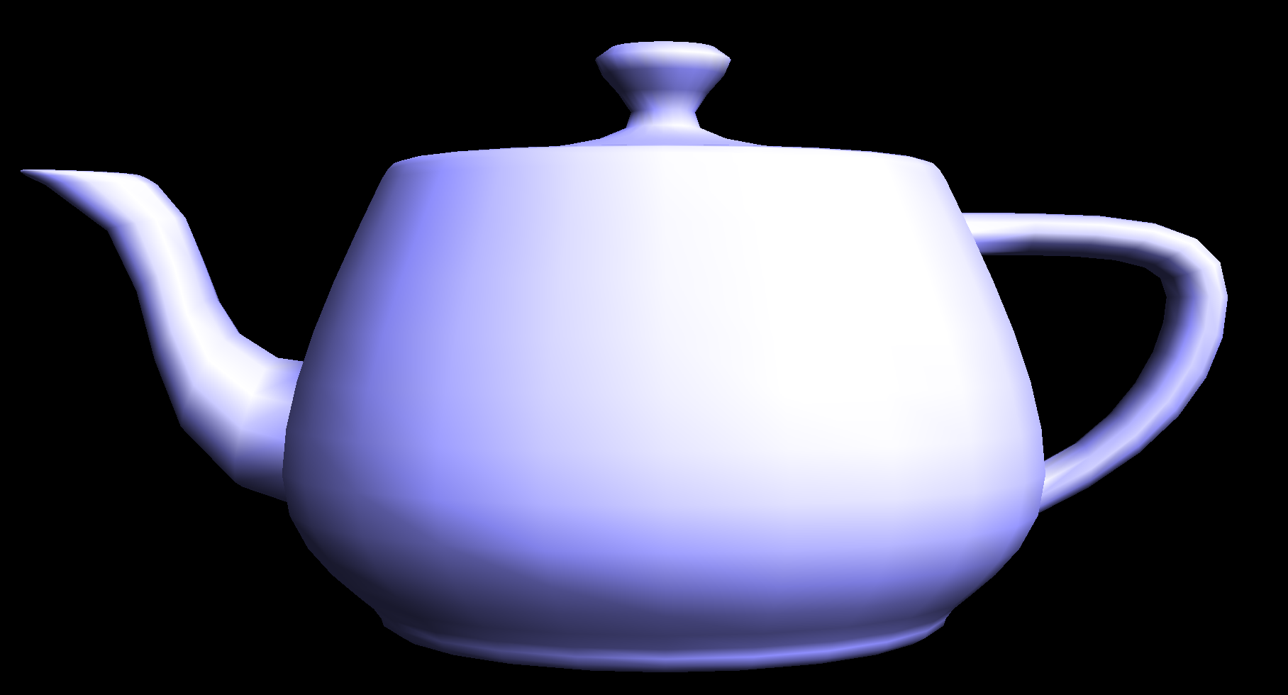 teapot render with averaged normals
|
Part 4: Half-edge flip
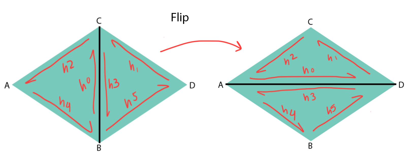
Next, I added the edge-flip functionality to my mesh editor. The operation consisted of reassigning half-edge pointers to vertices, faces, and other half-edges to flip an edge between two triangles, illustrated in the diagram below.
This did not involve adding any new elements. Instead, setting the next half-edge, twin, edge, face and vertex neighbors of all half-edges ensured that the edge would have the correct new neighboring elements post-flip. One mistake I made was assuming that all of the half-edges flipped in the same direction that the center edge did. After charting out a diagram, however, I realized that the only elements changing position were the two center half-edges. Every other element stayed in its original spot.
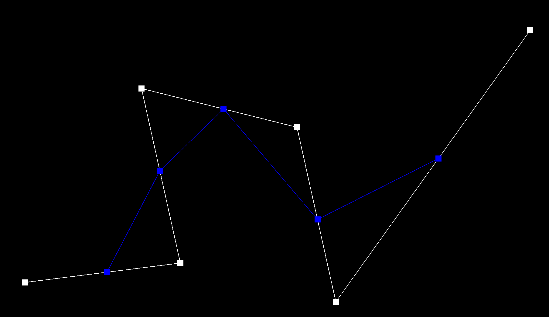
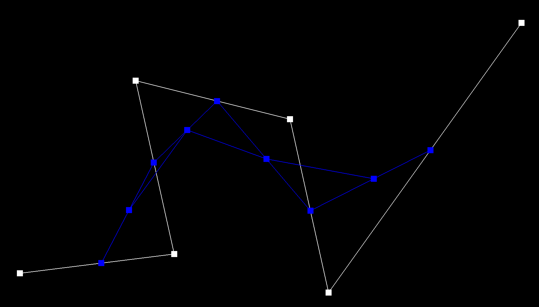
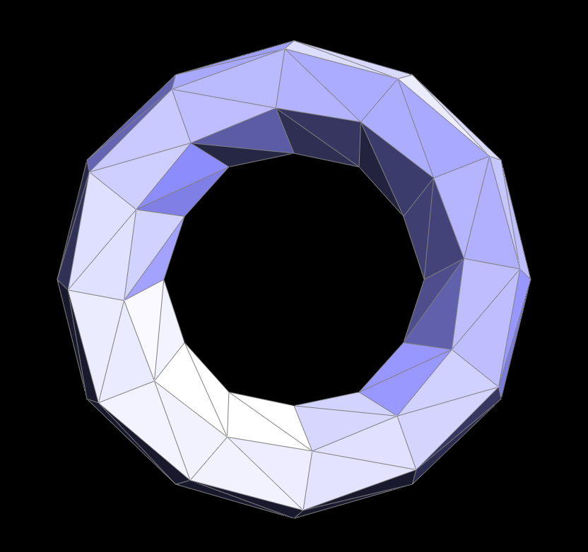
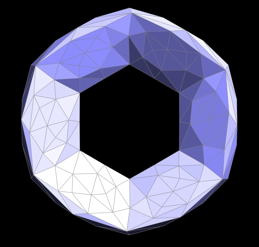
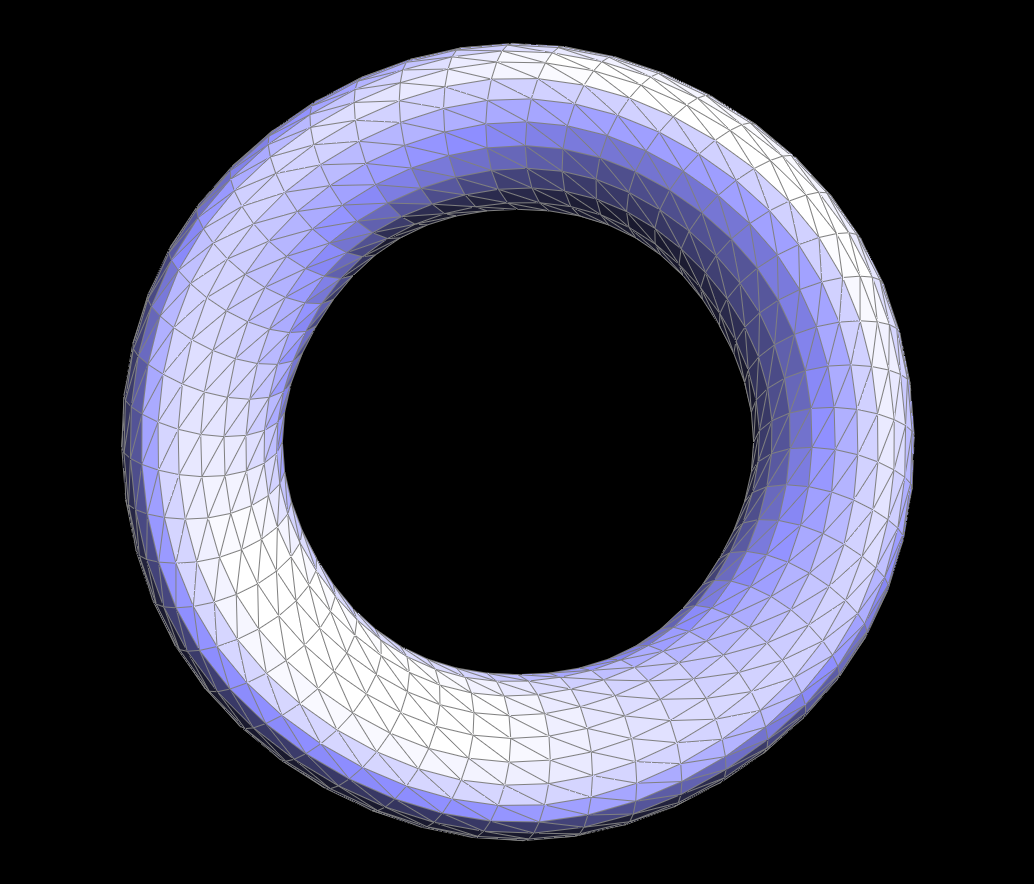
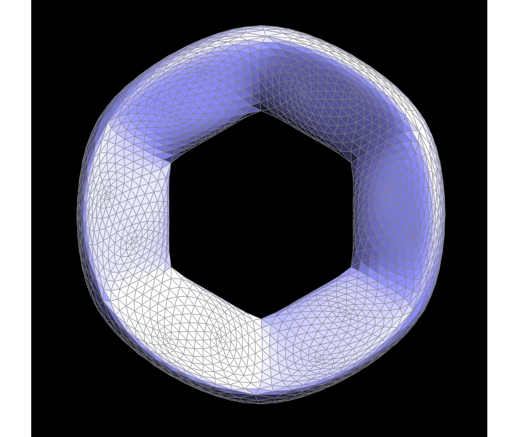
Below are before and after images of performing some edge flips on a torus mesh. By flipping the outer edge repeatedly on one half of the torus, some edges appear like they've collapsed. This actually caused the edges to flip to a position with much lower verticies, creating a neat effect.
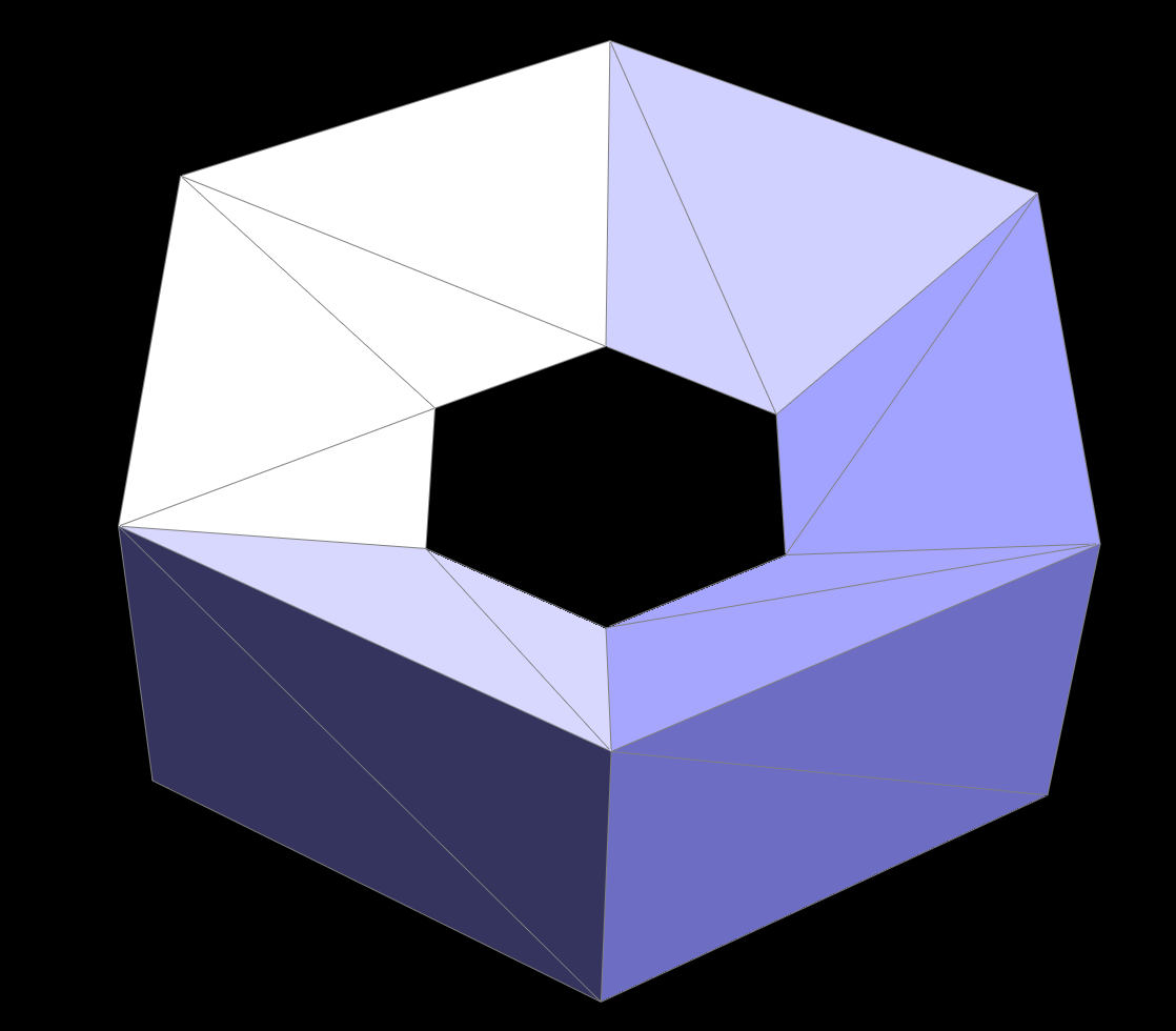 torus before edge flips
|
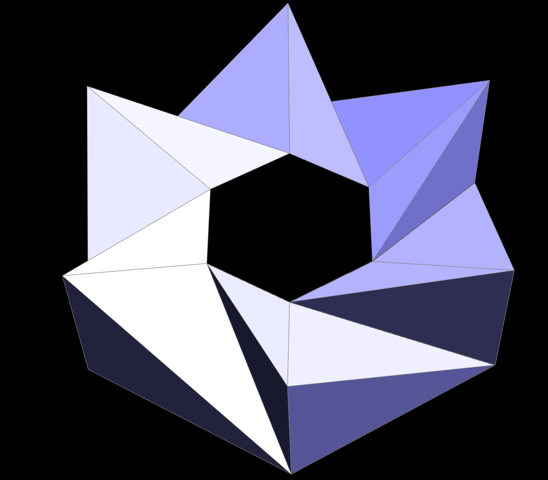 torus after some edge flips
|
Part 5: Half-edge split
The implementation of the edge split was more complex than the edge flip since it involved the addition of three new edges, six new half-edges, two new faces and a new vertex. Similar to the flip, I set the neighbors of each half-edge. Reassigning pointers was more lengthy for the split since many more half-edges needed to be reassigned to vertices, edges, and faces. Since I had a better grasp of the half-edge data structure at this point, I ran into less bugs than the flip. I reset every pointer, even if some things did not change, which ensured a much smoother implementation process.
Below are screenshots of the cow.dae file before and afer a series of edge splits.
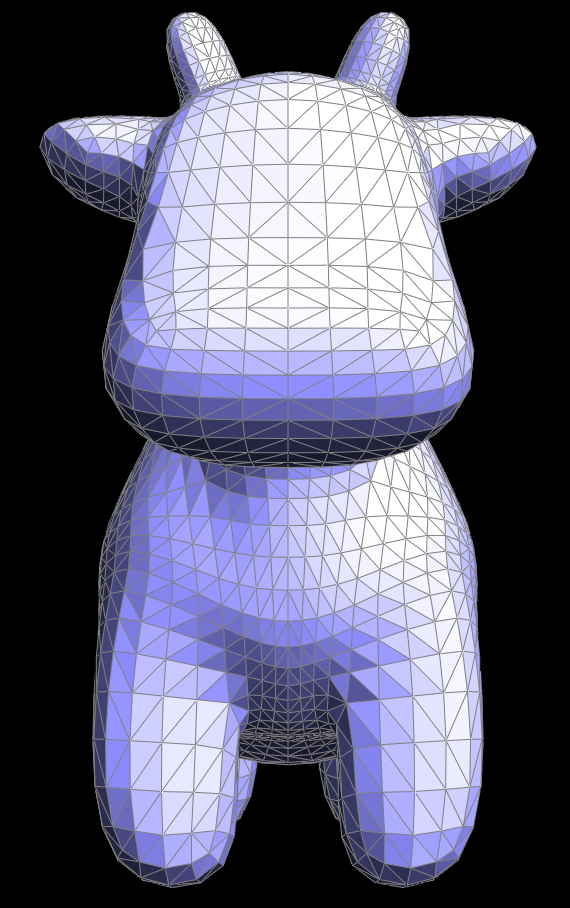 cow before edge splits
|
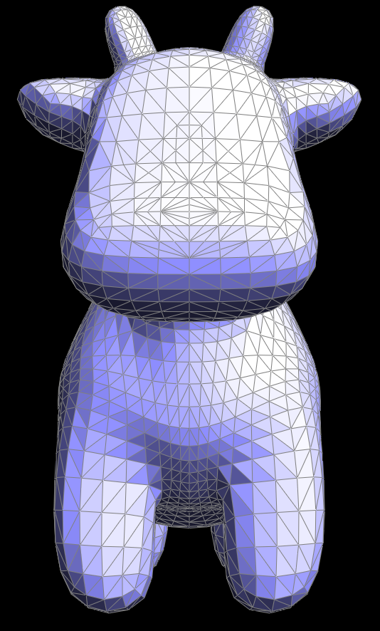 cow after some edge splits
|
These are before and after images of a series of flips and splits on the quadball.dae file.
 quadball before splits and flips
|
 quadball after a series of splits and flips
|
Part 6: Loop subdivision for mesh upsampling
Finally, I combined edge splits and flips to implement Loop Subdivision. The process consisted of taking weighted averages of vertices to determine their new positions as well as calculating the positions of new vertices and edges inserted with the subdivision. Each vertex and edge’s “is new” attribute was useful in determining whether/when to flip or split an edge. Setting all of the original edges’ and vertices’ “is new” to false initially helped distinguish them from new edges and vertices when edge splitting. I went through all of the edges in the mesh and split an edge only when its “is new” attribute was false to make sure I did not split any recently created edges. An issue I ran into at this stage was determining when to stop iterating through the edges. I started out with an infinite loop and fixed the problem by creating a counter keeping track of how many edges were split. I broke the loop when the counter reached the total number of edges in the mesh. The final step of Loop Subdivision was flipping all edges connected by a new and an old vertex. I used the “is new” attribute once again to check for old and new vertices. Next, I assigned new vertex positions based on saved calculations from the beginning of the process to achieve the new upsampled mesh.
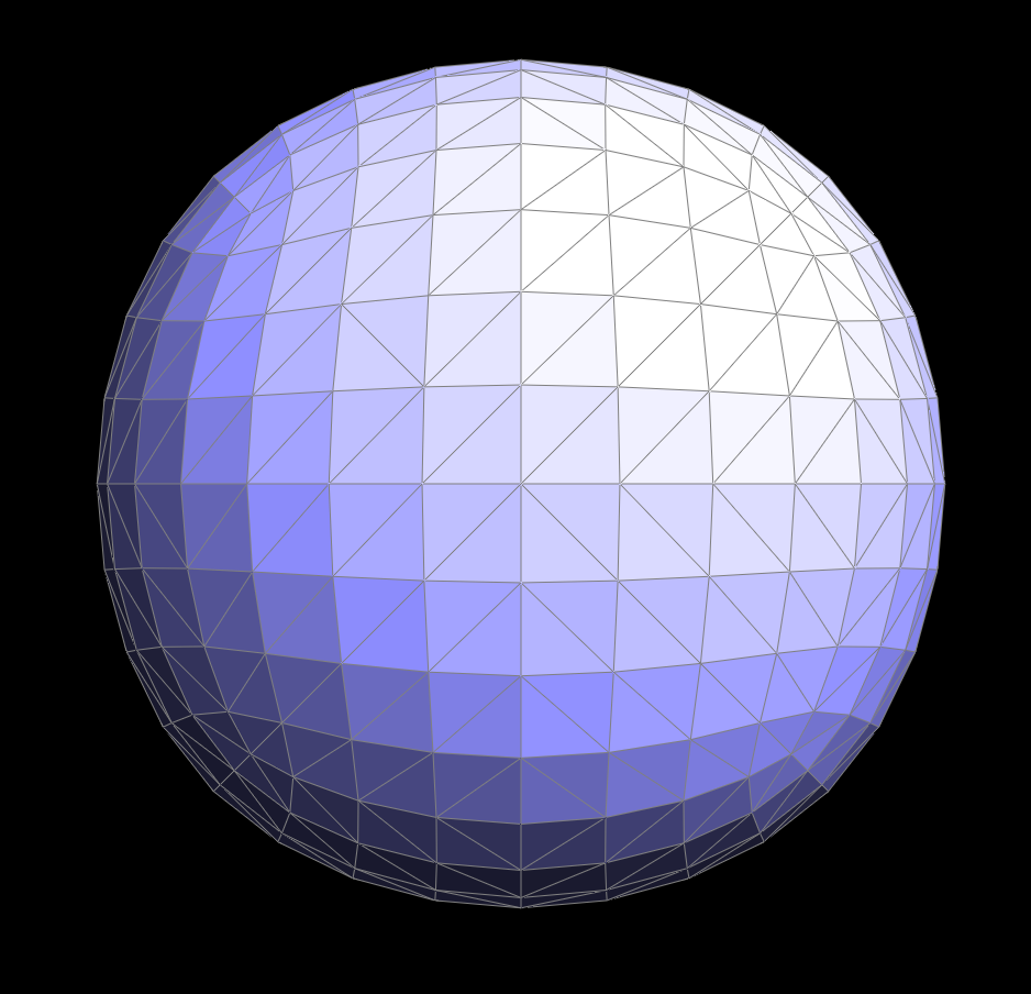
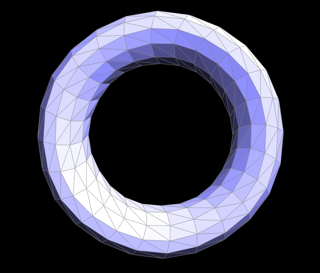
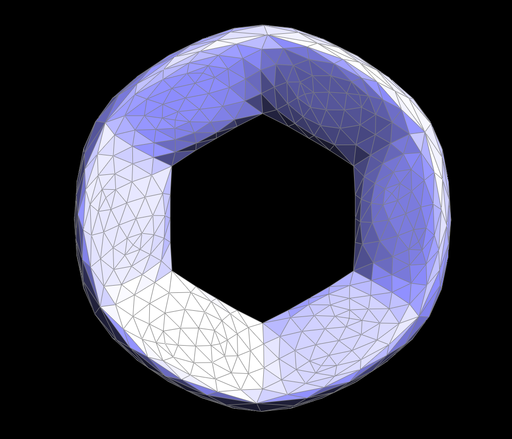
Upsampling geometry repeatedly causes edges to become less and less sharp because of weighted averages of new vertex positions. As a whole, the mesh becomes smaller and appears more compact. A torus, for example loses its edge structure and becomes a rounded donut shape. Pre-splitting or flipping edges can help lessen this effect by creating a smaller area for vertex weighted average calculations, exemplified in the screenshots below.
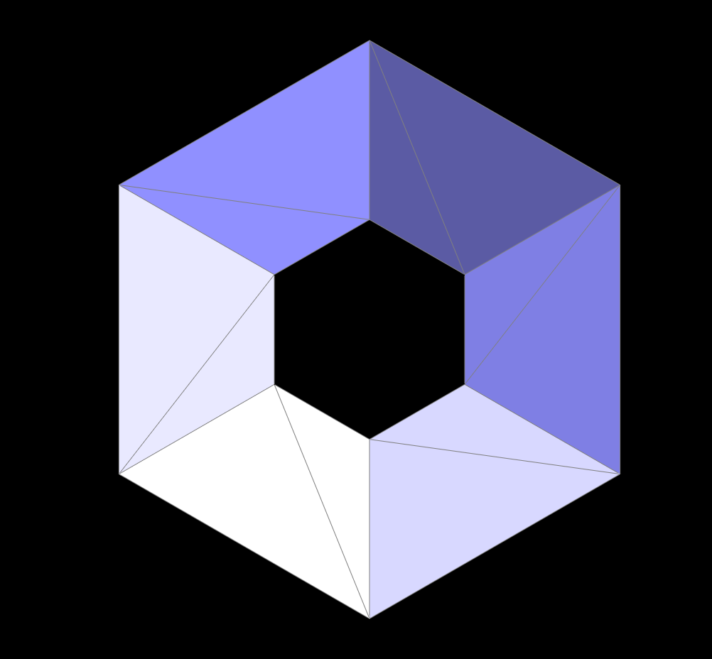 before upsampling
|
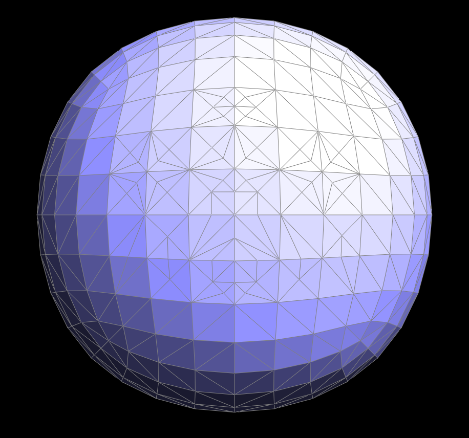
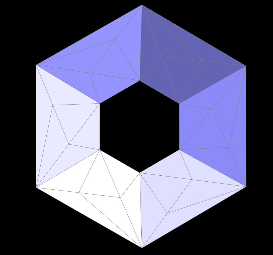 pre-split and flipped mesh before upsampling
|
 upsampled once
|
 pre-split upsampled once
|
 upsampled twice
|
 pre-split upsampled twice
|
 upsampled three times
|
 pre-split upsampled three times
|
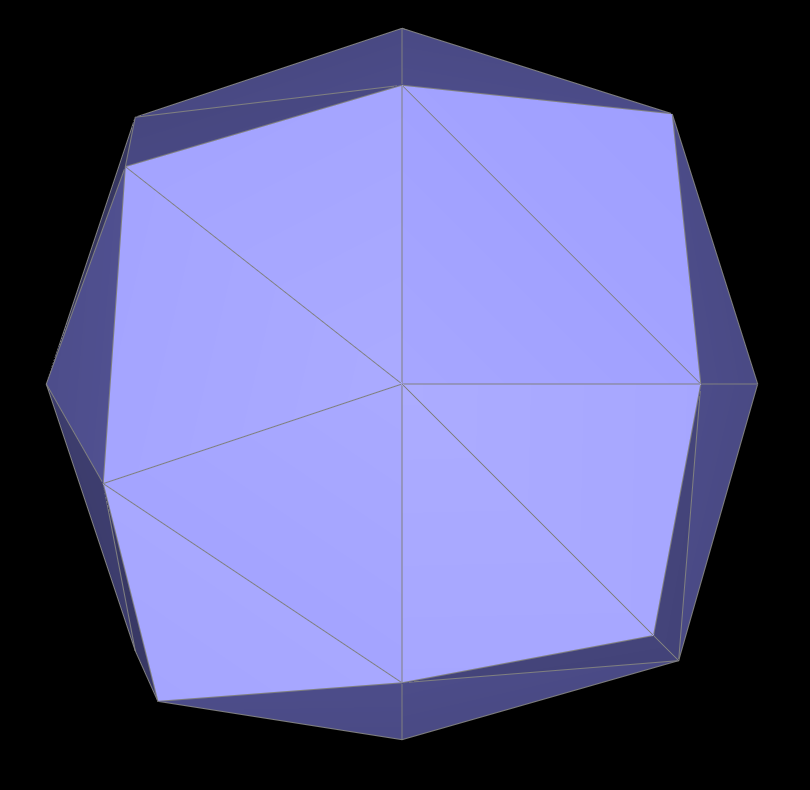
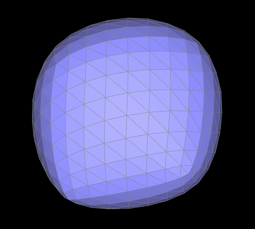
Some objects also lose symmetry when upsampling without any pre-splitting or flipping. The cube is initially split in with one diagonal through each face. This causes the cube to begin with asymmetric subdivisions, and when upsampled, becomes asymmetric in shape because of uneven averaging of vertex positions. By splitting and flipping edges on every face, the cube can be manipulated to have symmetric subdivisions to begin with. Thus, it maintains a symmetric shape when upsampled. This example also helps sharpen edges, as mentioned above.
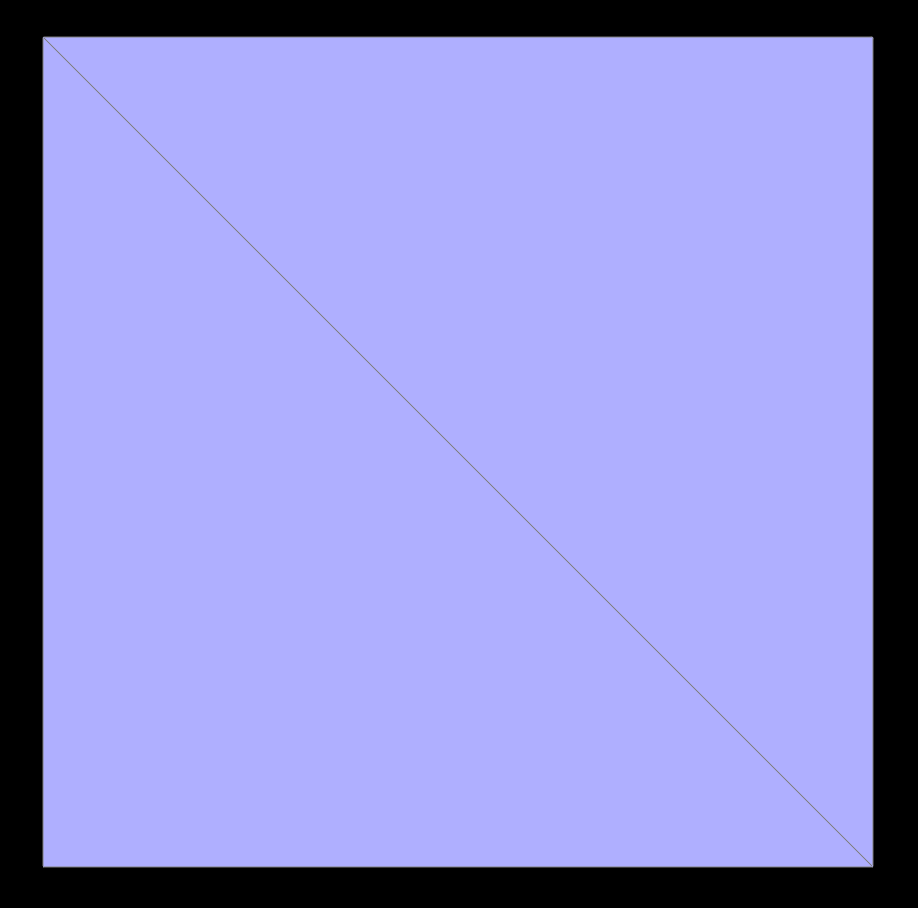 before upsampling
|
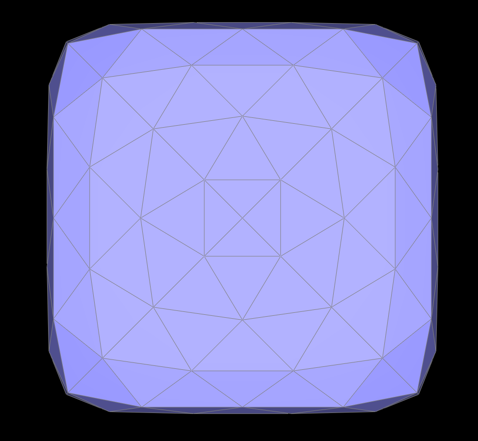
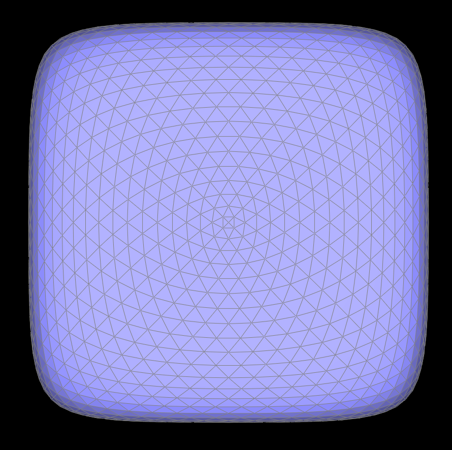
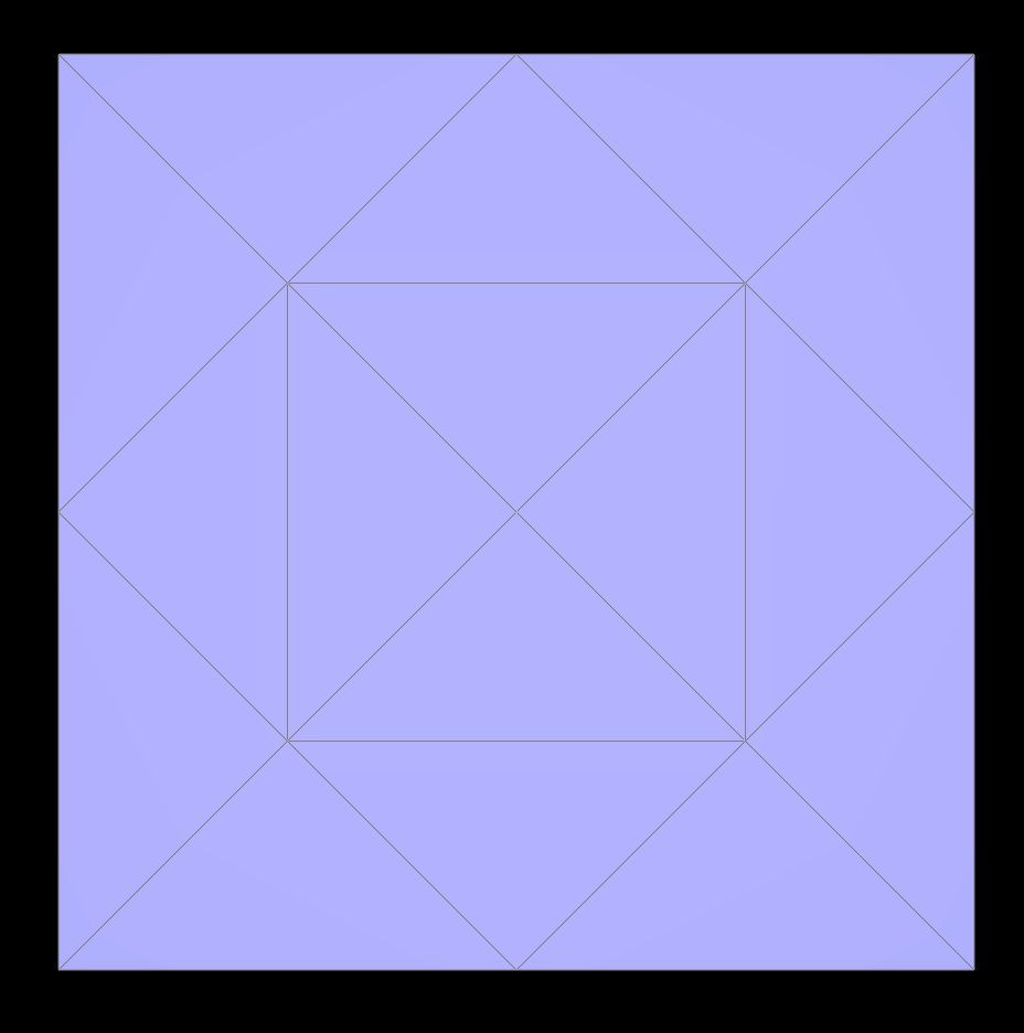 pre-split and flipped mesh before upsampling
|
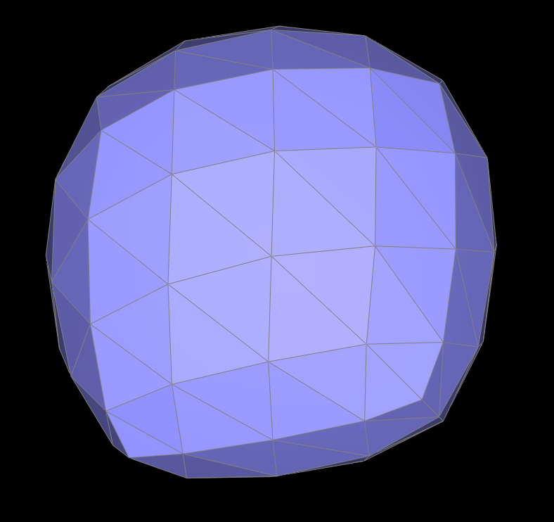
 upsampled once
|
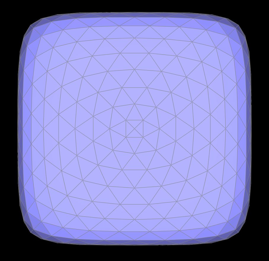
 pre-split and flipped upsampled once
|
 upsampled twice
|
 pre-split and fliped upsampled twice
|
 upsampled three times
|
 pre-split and flipped upsampled three times
|
Section III: Mesh Competition
Part 7: Design your own mesh!
I modeled an oski and flower mesh in Maya and exported them as .dae files. I began with basic cubes and extruded faces, moved verticies, and added a blinn shader for the export.
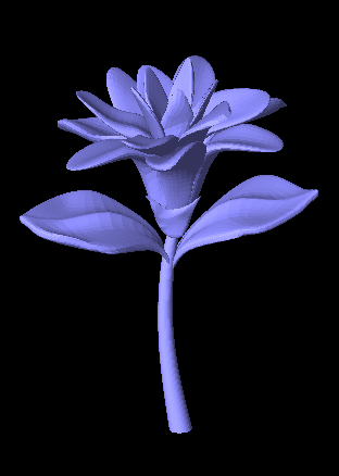 flower render
|
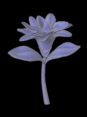 wireframe flower
|
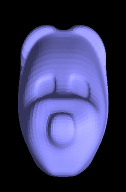 (slightly terrifying) oski render
|
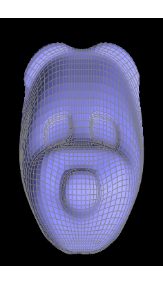 wireframe oski
|